20 14 Steps with Pictures Circuit Diagram
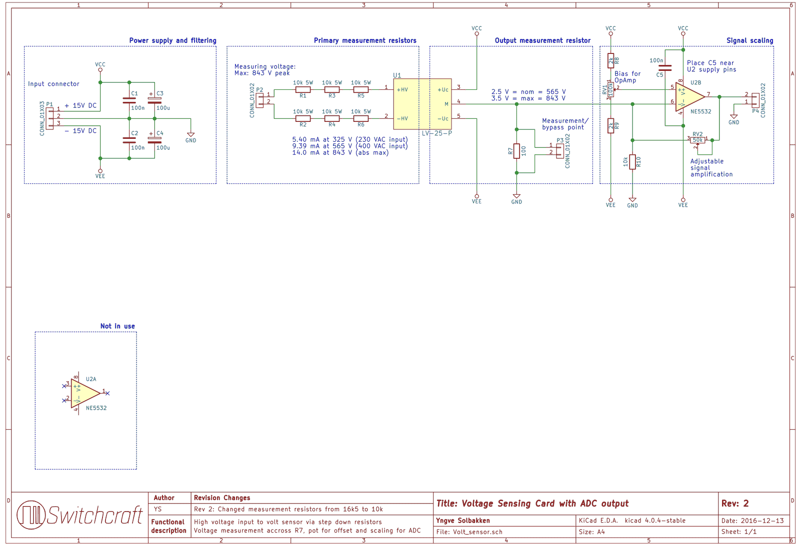
20 14 Steps with Pictures Circuit Diagram This project features a compact design and an all SMD component based circuit, making this sensor module very compact for it's range. This current sensor can easily be used for measuring currents up to 15 Amps constant and can even handle about 20 Amps peak.
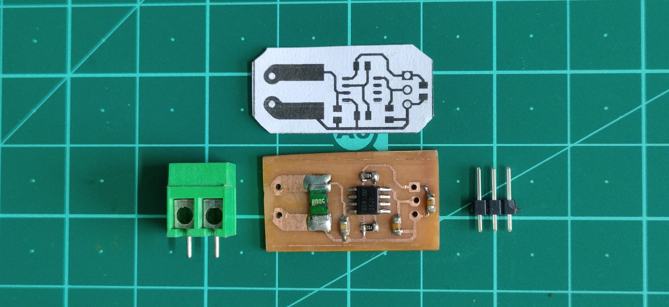
The idea is that you could build such a current sensor yourself and that's what this article is all about. The only hurdle is to measure low voltage drop. In the modules that I have dealt with so far, the shunt had a resistor of 0.1 ohms. Even with a fairly high current of, for example, an ampere, the voltage drop is just one hundred millivolts.
Current Sensing Circuit : 5 Steps Circuit Diagram
Assume that the required specifications of the low-side current detection circuit are as follows. Current sensing range: ILOADmin to ILOADmax = 30 A to 50 A Current sensing error: Err = 7% Current sensing frequency: fsense = 1 kHz Voltage drop at shunt resistor: ΔVSHUNTmax = 50 mV Maximum output voltage of the op-amp: VOmax = 3.3 V challenges associated with designing an accurate current-measurement circuit for cost-optimized applications. Approaches range from using general-purpose operational amplifiers to analog-to-digital converters, whether stand- This e-book was created to further simplify the current sensing design process by helping you quickly and efficiently
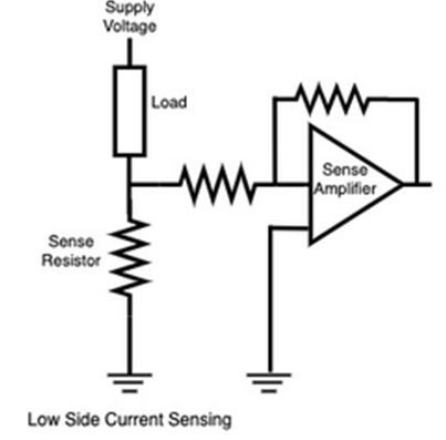
Current sensor circuits are used extensively in systems such as battery management systems in order to detect the current to monitor for overcurrent, a short circuit, and the state of charge of the battery system. so that you don't create a dangerous circuit. So how a current sensor works is that it's put in series with the circuit.

PDF Low Circuit Diagram
fundamentals of current sensing circuits. It introduces current sensing resistors, current sensing techniques and describes three typical high-side current sensing implementations, with their advantages and disadvan-tages. The other current sensing implementations are beyond the scope of this application note and reserved